ARC Valve for Industrial Systems
Centrifugal pumps, including those with an ARV (Automatic Recirculation Valve), are happiest when they move an adequate amount of liquid. Starve them at low flow and they heat up, vibrate, cavitate, and wear out. Force them to stop suddenly and the shaft sees damaging loads. Push them off their curve and you invite trips that ripple through a plant.
Our ARC Valve Categories
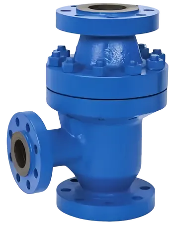
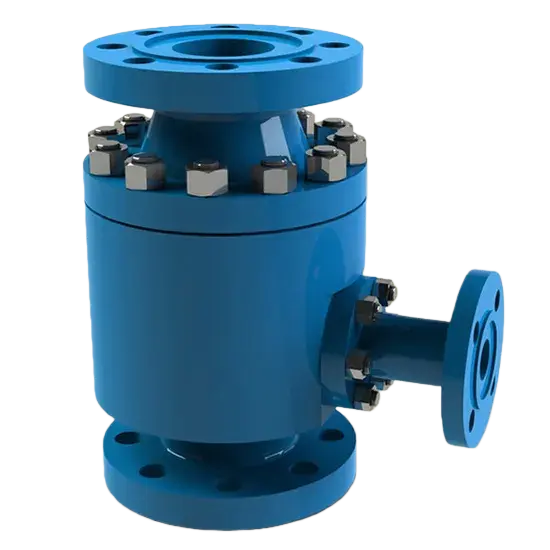
Cast Steel ARC Valve
Premium cast steel construction for high-pressure applications with excellent durability and corrosion resistance. Ideal for boiler feedwater, condensate extraction, and chemical processing systems.
- ASME Class 300-2500
- Temperature range: -29°C to 425°C
- WCB, WC6, WC9 materials
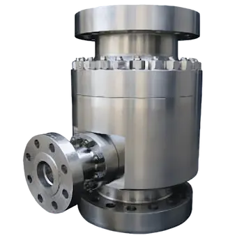
Forged Steel ARC Valve
Superior forged steel design for extreme service conditions with enhanced mechanical properties. Perfect for pipeline boosters, hydrocarbon charge pumps, and high-pressure desalination systems.
- ASME Class 600-4500
- Temperature range: -46°C to 565°C
- F11, F22, F91 materials
Get customized solutions for your specific requirements
Automatic Recirculation Valves for Pump Protection
An automatic recirculation valve, often shortened to ARC valve, and incorporating a non return valve, keeps pumps in a safe zone by sending a protective bypass flow whenever the main discharge falls too low. It does this without wiring, air supply, or a control loop. Just hydraulic forces and smart trim.
It looks simple on the outside. Inside, it is anything but.
What is an ARC Valve?
An ARC valve is a self-actuated, multi-function device installed on a pump discharge line, including a recirculation line, to ensure a minimum continuous flow through the pump. When process demand drops, the valve opens a bypass line that routes liquid back to a safe destination, commonly the suction source, a deaerator, or a low-pressure return. When process demand recovers, the valve closes the bypass and lets the full discharge go downstream.
Three functions, including flow modulation, are usually integrated in one body:
- Modulating bypass control based on the main flow rate
- Check valve action to prevent reverse flow through the pump
- Throttling and anti-cavitation staging in the bypass to manage pressure drop and noise
The valve is purely mechanical. Flow and pressure in the main line move an internal disc or piston against a spring. That motion controls an independent bypass trim sized for the pump’s minimum flow requirements.
Why Pump Protection is Necessary
A centrifugal pump is a thermal machine as much as a hydraulic one. At low flow, the energy put in by the impeller has fewer places to go, so it becomes heat and recirculating turbulence inside the casing. That combination drives several damaging effects.
- Temperature rise in the casing and seal chamber increases the risk of flashing at the eye, dry-running of mechanical seals, and accelerated elastomer aging.
- Internal recirculation at very low flow increases radial thrust, shaft deflection, and bearing load. That shortens bearing life and degrades seal faces.
- Net positive suction head available can drop locally due to vapor formation, creating cavitation pitting on impeller inlets and casing volutes.
- Vibration increases, which pushes the pump toward trip conditions and causes fatigue in supports and piping.
Pump vendors publish two important thresholds, usually on the curve or in the datasheet. Minimum continuous stable flow, which is the lowest flow where the pump runs smoothly for long periods, and a thermal minimum flow that avoids unacceptable temperature rise. Either value can dictate the recirculation requirement. The ARC valve is selected to maintain at least that flow automatically, independent of operator or DCS action.
Another silent risk is reverse flow during downstream upsets. Without a check element, a sudden downstream pressure surge can send liquid backward through the pump, spinning it the wrong way and damaging seals. ARC valves include a non-slam check function that closes quickly on backflow.
ARC Valve Working Principle
An ARC valve links the main flow path and a bypass path through a mechanically coupled trim. The device senses the main discharge flow indirectly through differential pressure across an internal restriction or by velocity-induced forces on a disc. That motion is translated into a position change in a bypass plug or lift element.
The genius lies in the kinematics. The more main flow you have, the less bypass is allowed. At a preset main flow point, the bypass closes completely and the unit becomes a low-loss check valve.
Main Flow and Bypass Flow
- At startup or low process demand: The main line velocity is low, the internal disc moves to a position that opens the bypass fully or partially, and liquid returns to a low-pressure point. This keeps the pump cooled, lubricated, and running near a stable region of its curve.
- During normal operation: As process demand increases, the valve senses higher flow, which shifts the internal disc and progressively throttles the bypass. The main flow path opens wide with low pressure drop.
- During trips or downstream surges: The check element snaps shut to block reverse flow into the pump, protecting impeller and shaft from reverse rotation.
The bypass section is not a simple hole. It often uses staged orifices, multi-turn cages, or multi-step trims to manage large pressure drops without cavitation. Materials and geometry are engineered to survive erosive bubbles and noise in the bypass.
Modulating Disc Operation
The modulating element inside an ARC valve, such as an actuator, can be a disc, piston, or cone driven by differential pressure across a nozzle or Venturi. Spring forces and hydraulic forces reach equilibrium in a way that maps main flow to bypass opening. Key behaviors:
- At zero main flow, spring positioning keeps the bypass wide open.
- As main flow increases, the hydraulic force on the disc overcomes the spring, moving the mechanism to reduce bypass. The relationship is designed so that at the minimum flow setpoint the bypass is still passing enough liquid to meet pump needs.
- At a defined main flow, the bypass fully shuts, and the path to the process is essentially unobstructed.
- During backflow, the check feature closes the main path quickly, independent of bypass modulation.
No external calibration in the field is required. Setpoints are baked into the trim geometry and spring selection during sizing.
Technical Parameters Overview
| Parameter | Cast Steel ARC Valve | Forged Steel ARC Valve |
|---|---|---|
| Size Range | 2″ – 24″ (DN50 – DN600) | 1″ – 16″ (DN25 – DN400) |
| Pressure Class | ASME 300 – 2500 | ASME 600 – 4500 |
| Temperature Range | -29°C to 425°C | -46°C to 565°C |
| Body Materials | WCB, WC6, WC9, CF8, CF8M | A105, F11, F22, F91, F316 |
| End Connections | Flanged (RF, RTJ), Butt Weld | Flanged (RF, RTJ), Butt Weld, Socket Weld |
| Trim Materials | Stellite, 17-4PH, Monel | Stellite, Inconel, Hastelloy |
| Flow Characteristic | Linear / Modified Equal % | Linear / Modified Equal % |
| Bypass Cv Range | 5 – 500 | 2 – 350 |
| Leakage Class | ANSI Class IV (standard), V (optional) | ANSI Class V (standard), VI (optional) |
| Standards Compliance | ASME B16.34, API 598 | ASME B16.34, API 598, NACE MR0175 |
Key Features and Benefits
ARC valves have earned their place on critical pumps because they concentrate several protections into a compact envelope.
Self-actuated operation
No instrument air, power, or control logic required
Built-in minimum flow protection
Satisfies pump vendor requirements even if the control system is unavailable
Integrated non-slam check
Prevents reverse rotation and protects seals and bearings
Quick response
Mechanical linkage reacts within the pump’s thermal time constants
Robust bypass trim
Staged pressure reduction to tame cavitation, flashing, and noise
Low mainline loss
Minimal pressure drop when the bypass is shut, helping pump efficiency
Compact footprint
Replaces multiple components and simplifies piping
Fail-safe bias
Spring action favors a safe bypass-open state when main flow is low
Selection Options
- Pressure classes from ASME 300 to 2500, with butt-weld or flanged ends
- Materials including carbon steel, low alloy steel, stainless, duplex, and specialty alloys
- Bypass capacity matched to minimum continuous flow and thermal limits
- Soft or metal seats depending on fluid and temperature
- Orientation options suited to horizontal or vertical lines
Applications of ARC Valves
Critical pumps that face low demand periods stand to gain the most, benefiting significantly from centrifugal pump protection in a valve operation scenario. You will see ARC valves almost anywhere a multistage pump meets a system with variable flow.
Important Considerations: The bypass return location matters for components like an actuator. For boiler feedwater, a common choice is the deaerator or a low-pressure tank where heat can dissipate safely. For hydrocarbon services, the return should avoid flashing into vapor clouds, so routing to a suction drum with adequate NPSH margin is common.
Plant designers also consider acoustics. High-pressure drops across the bypass can generate noise if not staged properly. Modern trims handle this well, but confirm the expected sound power and choose materials that resist cavitation erosion.
ARC Valve vs. Control Valve Systems
Engineers sometimes weigh an ARC valve against a traditional minimum flow control loop that includes a flow transmitter, a PID loop, an ARV, a recirculation line, and a control valve on the bypass line. Both approaches can work. The choice hinges on reliability goals, flexibility needs, and lifecycle cost.
| Aspect | Self-actuated ARC valve | Instrumented control loop |
|---|---|---|
| Power and utilities | None required | Needs power and often instrument air |
| Response to trips | Instant mechanical action | Depends on loop tuning and device speed |
| Failure modes | Spring bias opens bypass at low flow | Device or signal failure can leave valve shut or open |
| Complexity | Single device with integrated check | Multiple devices and wiring, more points of failure |
| Mainline pressure drop | Very low at full flow | Depends on additional fittings and check valve |
| Setpoint flexibility | Fixed by trim and spring | Adjustable from control system |
| Turndown of bypass | Sized for required minimum only | Can be modulated for process needs |
| Maintenance | One device to service | Transmitters, positioners, and valve maintenance |
| Capital cost | Moderate, often lower in total | Higher due to instruments and installation |
| Diagnostics | Limited, mostly mechanical inspection | Rich data from transmitters and control system |
Plants with a highly dynamic minimum flow requirement may favor a control loop, especially when integrating a non return valve to prevent backflow, considering the valve operation scenario. Most pump protection duties, including centrifugal pump protection, call for a predictable, always-available safeguard, which is where ARC valves excel.
Frequently Asked Questions
What information is needed to size an ARC valve?
- • Pump curve and the minimum continuous stable flow
- • Normal and maximum discharge flow
- • Suction pressure, discharge pressure, and temperature
- • Fluid properties, including vapor pressure and viscosity
- • Required return destination and pressure
- • Materials of construction and pressure class
Where should the bypass return?
- • To a location that stays well below the pump discharge pressure so the bypass can pass the required flow
- • To a destination that can absorb heat without causing flashing, for example a deaerator, suction drum, or low-pressure tank
- • To a point with adequate NPSH margin if it rejoins the suction, to avoid vapor carryover
Can an ARC valve prevent cavitation entirely?
- • It prevents cavitation inside the pump by maintaining minimum flow
- • In the bypass, cavitation is addressed by multi-stage trim and material selection, which are designed to tolerate high pressure drops
- • Proper sizing and return pressure control are still important
How does it differ from a simple orifice bypass?
- • An orifice wastes energy continuously by bypassing flow even at full demand
- • An ARC valve bypasses only when needed and closes tightly at normal operation, improving efficiency
- • The check function and staged trim in an ARC valve also add protection that an orifice cannot provide
Can an ARC valve protect against deadhead?
- • Yes. At zero system demand, the bypass opens to pass the minimum flow and avoid a deadhead condition
- • If the return path is blocked, the protection is compromised, so keep the bypass line open and monitored
What about dirty or particulate-laden fluids?
- • ARC valves are better suited to clean liquids
- • For services with solids, consider filtration upstream, hardened trims, or alternative centrifugal pump protection methods
- • If solids are possible during upset, an ARV trim tolerant of erosion, a non return valve, and an actuator-controlled bypass return that avoids sediment traps are wise
Designers who match an ARC valve to the pump’s curve, pick a safe return point, and respect fluid properties based on a detailed valve operation scenario end up with a safeguard that works quietly for years. It is a small device that delivers big insurance for critical rotating equipment.
Technical Documentation
Download our comprehensive technical resources to learn more about ARC valve specifications and applications.
Technical Brochure
Complete technical specifications, sizing guidelines, and application data for ARC valves.
Sample Drawing
Detailed dimensional drawings, installation guidelines, and typical P&ID configurations.
Request a Quote or Technical Support
Our experts are ready to help you select the right ARC valve for your application
Quick Response
24-hour technical support
Global Service
Worldwide delivery available
Quality Certified
ISO 9001:2015 certified