Valve Symbols: Essential Knowledge for Engineers
Master the language of engineering drawings and transform complex diagrams into clear instructions
Valve symbols look like a secret language until you see the patterns. Once you do, drawings turn into clear instructions for fabrication, maintenance, and operations.
This guide gives you a practical way to read and apply valve symbols with confidence, whether you are building a P&ID set, reviewing a vendor print, or troubleshooting in the field.
Why valve symbols matter
Valve symbols compress a lot of decisions into a few strokes on a page. They speed up reviews, reduce ambiguity during construction, and make future modifications far easier.
A good symbol tells you:
- What type of valve it is
- How many ports it has
- How it is actuated
- What its normal position is when power or air is removed
- Any special function like check, relief, or throttling
- What the tag means in relation to the loop or system
Modern plants live or die by how clearly the design communicates. Valve symbols are small, but the impact is large.
Engineering diagrams with valve symbols and P&ID specifications
Standards and the many drawing dialects
Two broad families of symbols show up most often.
-
Process and instrumentation diagrams (P&IDs): ISA 5.1 is the common reference in North America. ISO 14617 also appears in global projects. These drawings emphasize process equipment, manual valves, control valves, and instrumentation.
-
Fluid power schematics: ISO 1219 and ISO 5599 guide hydraulic and pneumatic symbols. These focus on directional control, pressure control, and actuator logic.
Some regions apply local tweaks, and some companies publish their own legend. That legend rules the project. If you inherit an unusual set, start with the legend and tag list.
Anatomy of a valve symbol
Once you know what to look for, most symbols fall into place.
Body shape
Hints at the valve family. A simple gate-like line, a circular ball, or a butterfly disc.
Ports and ways
Two ports for inline isolation, three for diverting or mixing, four or five for directional control in fluid power.
Internal elements
A check flap, a spring for biasing, or a spool path inside boxes for directional valves.
Actuation
A handwheel, lever, gear operator, pneumatic diaphragm, electric motor unit, or solenoid.
Normal position
The state with no power, no air, and no external force. Marked by spring symbols or by which box is at rest in directional schematics.
Accessories
Positioners, limit switches, volume tanks, and regulators drawn near the actuator.
One more tip: Orientation on the page often does not change function. If a check valve triangle points left or right, the meaning is defined by the arrow relative to flow, not by cardinal direction.
Common manual valve symbols and what they imply
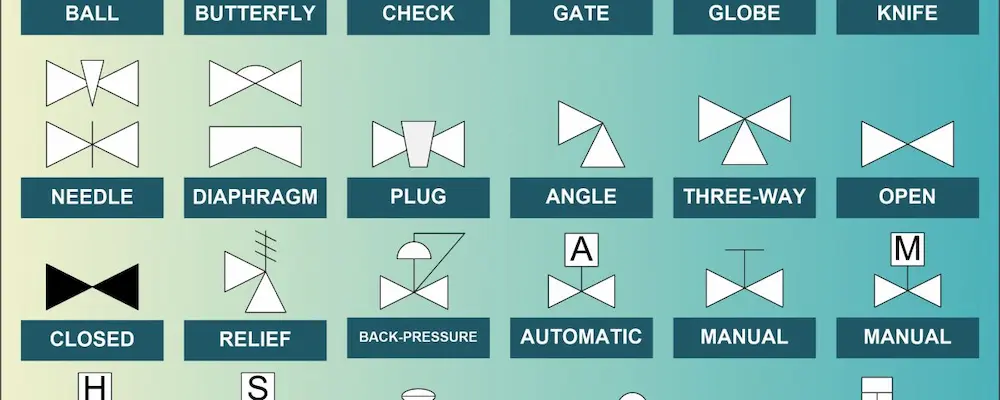
Here is a concise cheat sheet for P&ID style symbols. The descriptions are text based to help you visualize what to look for in a legend.
| Valve type | Symbol cues you will see in a P&ID legend | Typical service area | Notes that help in the field |
|---|---|---|---|
| Gate | A straight line across the pipe | Isolation on clean liquids | Low pressure drop when open, not for throttling |
| Globe | Curved seat or orifice in the body | Throttling, control | Good for control, higher pressure drop |
| Ball | Circle inside body with a straight bore | Quick isolation, gas, slurries | Quarter turn, tight shutoff |
| Plug | Tapered plug shape | Chemical services, isolation | Quarter turn, can be lubricated or sleeved |
| Butterfly | Disc across a circle | Large diameter water or air | Quarter turn, compact, moderate shutoff quality |
| Diaphragm | Flexible membrane shown as a line/arc | Corrosive or dirty media | Good sealing, limited temperature and pressure |
| Pinch | Rubber tube pinched by bars | Slurries, solids in suspension | Straight through bore, gentle on media |
| Check (swing) | Flap or hinged disc with arrow | Backflow prevention | No external actuator, gravity or spring assisted |
| Check (lift) | Spring-loaded poppet | High pressure clean fluids | Better for pulsating flow |
| Relief/safety | Spring on a poppet with outlet to vent | Overpressure protection | Set pressure and blowdown critical |
| Strainer | Screen or Y-body with mesh symbol | Protects downstream equipment | Sometimes combined with a blow-off valve |
A symbol rarely tells you materials or class ratings. That comes from the callout balloons, line lists, and valve schedules.
Multiport and directional control valves
When you shift to hydraulics or pneumatics, the drawings look different, especially with the use of detailed valve symbols to represent various functionalities. You will see boxes with arrows and T shapes inside them. Each box shows a valve position. The active position is the one with the spring on the opposite side or the one not acted on by the solenoid. Arrows show permitted flow paths, T indicates a blocked port.
Common patterns:
- 2/2 valve: Two ports, two positions. Often used as an on-off valve for air or oil.
- 3/2 valve: Three ports, two positions. Feeds and vents an actuator port.
- 4/2 or 5/2 valve: Four or five ports, two positions. Drives double-acting cylinders.
- 4/3 valve: Four ports, three positions. Center position can be closed, open, or pressure centered.
Port letters often appear:
- P or pressure port: supply
- A and B: work ports to the actuator
- T or R: tank or return
Actuation is shown by a small box at the end of the valve symbol. Common items include a solenoid coil, a pilot line triangle, or a lever. A spring symbol returns the spool to its normal state when the actuation force is removed.
Two reading rules keep you out of trouble:
- Trace the lines, not just the shapes. A line into a box may be a pilot line that switches the valve at a set pressure.
- Identify the normal position. Many mistakes come from assuming the left box is the active one. Look for the spring symbol.
Actuation methods and how they are drawn
Manual operation:
Circle or wheel drawn on a stem. Smooth throttling when combined with globe bodies.
Simple lever icon on a stem. Quick quarter turn for ball and butterfly.
Gearbox block with a handwheel. Used on large torque valves.
Handwheel with a chain loop for overhead valves.
Powered operation:
Round actuator above or beside the body. Often shown with a spring to indicate fail state.
Small box with a motor symbol and conduit connection. Often includes limit switch symbols.
Cylinder icon with fluid connections to a power unit.
Accessories you might see:
- Positioner: A small square on the actuator with an instrument connection from an I/P converter or control loop.
- Limit switches: Small boxes on the yoke with electrical connections to a junction box.
- Booster or volume tank: On fast stroking valves, drawn near the actuator air line.
Fail positions are usually labeled:
fail open
fail closed
fail last
A spring on the actuator side shows which way it drives when air or power is lost. Double-acting actuators might hold position if the system includes a lockup relay or a bypass. That detail often sits in the instrument index or a valve data sheet.
Control valve symbols in P&IDs
Control valves combine the valve body type and an actuator with instrumentation callouts. The circle-and-tag bubble indicates the loop. The letters follow ISA convention.
- First letter: measured variable. F for flow, P for pressure, T for temperature, L for level, A for analysis.
- Second letter: readout or function. I for indicator, C for controller, T for transmitter, V for valve as a final element.
- Number: loop number that ties all elements together.
Examples you may see on a drawing:
The body symbol inside the line usually hints at the valve type, and valve symbols play a crucial role in identifying various valve types. A globe body suggests throttling service, a ball body suggests on-off with possible modulating trim. An arrow across the valve body is not a flow direction arrow, it often marks a control element. Follow the legend for your project.
Trim and characteristics rarely appear in the symbol. Those live in the valve schedule:
- Equal percentage vs linear characteristic
- Cavitation and noise trim
- Flow direction preference for control stability
See the valve specification to confirm these details before procurement.
Reading check valves, reliefs, and special functions
Check valves block reverse flow. A triangle or flap points in the allowed flow direction. If a spring is drawn, the valve closes at zero flow and opens once differential pressure exceeds the spring force.
Relief and safety valves protect equipment
The symbol shows a spring pushing on a poppet with an outlet to a safe location.
Opens gradually around setpoint, often adjustable.
Pops open near setpoint, common on steam and gas.
Sight glasses, bleed valves, vents, and drains populate the small details on P&IDs. A small valve symbol on a tee branch pointing up is often a vent. Down is often a drain. These are critical during commissioning and maintenance.
Multiport process valves
Three-way and four-way process valves show up on diverter and mixer services.
One inlet, two outlets. Symbol often shows a Y body or a plug with two paths.
Two inlets, one outlet. Similar body shape but reverse flow.
Used in some HVAC reversing functions or complex batch duties.
The tag or note should state the function, for example DIV or MIX. The control narrative decides which port is the normal path.
Tagging, callouts, and what to read beyond the symbol
The valve symbols are one piece of the puzzle. The callouts around them seal the deal.
Tag bubble
Ties to an instrument index or valve list with all properties and vendor data.
Line number
Gives pressure rating, material, insulation, and heat tracing information.
Size and rating
NPS or DN, pressure class, flange type, end connection.
Notes
Special cleaning, oxygen service, cavity relief holes on ball valves, torques, stroke times.
Before you approve a design, confirm that the symbol, tag, and schedule tell a consistent story.
Small field guide: mistakes that cause rework
A few common pitfalls show up again and again.
The symbol may be rotated to fit the page. The legend defines its meaning.
Without power or air, what happens? This affects interlocks, startups, and maintenance.
A check allows one-way flow based on differential pressure. A relief opens at a set pressure to protect equipment.
FO vs FC is not a minor detail. Plant safety and process stability depend on it.
Globe valves can isolate, but seat wear rises in dirty service. A ball or gate might be better for shutoff.
A motor operated valve on a small line may require a support detail to avoid nozzle loads.
Every project can tweak symbols. The legend is part of the contract.
Quick reads for common scenarios
Water distribution header upgrade
Butterfly valves on large diameter lines, check valves on pump discharge, air release valves at high points.
Choose gear operators for large butterflies, verify check orientation, add drains at low points for hydrotest.
Steam letdown station
Globe control valve with pressure controller, safety valve to a vent header, drip legs with steam traps.
Mark flow direction across the control valve per vendor, place safety valve upstream of isolation where required by code, include bypasses where operations requests it.
Compressed air actuator circuit
5/2 solenoid valve with spring return, filter-regulator-lubricator, double-acting cylinder, quick exhaust.
Confirm which end is the normal position by the spring, trace P to A and B in each position, check exhaust mufflers for noise.
Chemical dosing skid
Diaphragm pump, check valves on suction and discharge, relief valve to a return line, isolation ball valves.
Ensure checks are compatible with fluids, set relief pressure below pump deadhead, add calibration column if required.

Automated valve control system in industrial facility
Drawing clarity: small choices that raise quality
On a busy set, clean symbology, including the precise use of valve symbols, turns hours of review into minutes.
Do not let a check valve look like a relief in your legend.
HV for hand valves, MOV for motor operated, PSV for relief, SDV for shutdown, XV for generic isolation.
A single line of text can prevent a startup incident.
Loops tell the story of control.
Readers can find materials, ratings, trims, and torque values.
How to audit a valve on a P&ID or schematic
Use this quick checklist when you see a valve on a drawing:
- Identify the valve types and their family: isolation, control, check, relief, directional.
- Count ports and positions.
- Determine actuation and fail state.
- Read the tag and cross-check the schedule.
- Confirm line rating compatibility.
- Note special service needs stated in the notes.
- Verify support or access impacts if the operator is large.
- Look for vents, drains, and bypasses near the valve.
Two minutes spent here can save days later.
Comparing symbol sets during cross-discipline reviews
Process, mechanical, electrical, and controls teams each view symbols through their own priorities. When you run an interdisciplinary check:
Controls Lead
Confirm loop numbers and fail states for control valves and SDVs.
Mechanical
Confirm body types match the service and materials.
Electrical
Verify motor operators have the right enclosure ratings and power feeds.
Process
Verify pressure relief coverage, including setpoints and relief destinations.
A short huddle around the legend can prevent conflicting assumptions.
Practical notes on valves that often trip teams
Ball valves in fire safe service often need cavity pressure relief holes. The symbol will not show it. The schedule must.
Cryogenic valves need extended bonnets. Look for this note near the valve or in the equipment list.
Double block and bleed can be a single valve with two seats or two valves with a bleed between them. The symbol should match the design intent and safe isolation policy.
Butterfly valves upstream of pumps can cause uneven velocity profiles. Drawings should include notes on straight run or flow conditioning if pump vendor requires it.
Globe control valves prefer a flow direction. Many vendors mark preferred flow to close or flow to open. Coordinate with the fail state.
A mini glossary for consistent communication
A few short definitions keep teams aligned.
The state when all external power and instrument air are removed.
The position a valve moves to when it loses its driving force.
Device that compares control signal to valve position and adjusts actuator pressure.
Identifier that ties transmitters, controllers, and final elements into one control function.
Valve that routes fluid power to actuator ports according to its position.
Opens at set pressure to protect equipment, reseats once safe pressure returns.
A one-page reference you can print
Valve Types:
- Gate: isolation, low pressure drop, not for throttling
- Globe: throttling, control, higher pressure drop
- Ball: quarter turn, tight shutoff, fast operation
- Plug: quarter turn, compact, chemical duty
- Butterfly: quarter turn, large diameters, moderate shutoff
- Diaphragm: clean and corrosive services, limited temperature
- Pinch: slurries, straight bore
- Check: one-way flow, spring or gravity assisted
- Relief/safety: overpressure protection, setpoint critical
- Strainer: upstream protection, blow-off if needed
Directional Symbols:
- Boxes show positions, arrows show flow paths, T bars mean blocked
- Spring marks normal state
- Solenoid or pilot marks what moves the spool
Actuation and States:
- Manual, pneumatic, electric, hydraulic
- FO, FC, FL marked in notes or tags
- Accessories: positioner, limit switches, boosters
Reading Order:
- Identify type
- Find ports and paths
- Confirm actuation and normal
- Check tag, schedule, and service notes
With a steady approach, the symbols stop being cryptic marks and start reading like clear instructions.
Need Expert Valve Solutions?
If you’re looking for high-quality valves or need expert engineering support, we’re here to help.
Request a QuoteFrequently Asked Questions (FAQ)
1. What are valve symbols and why are they important?
Valve symbols are standardized graphical representations used in engineering drawings and schematics to depict different types of valves. They are essential for clear communication, ensuring that engineers, technicians, and operators understand the type and function of each valve in a system.
2. Where are valve symbols commonly used?
Valve symbols are widely used in process flow diagrams (PFDs), piping and instrumentation diagrams (P&IDs), and technical documentation across industries such as oil and gas, chemical, water treatment, and manufacturing.
3. Are valve symbols standardized internationally?
Yes, valve symbols are standardized by organizations such as the International Organization for Standardization (ISO) and the American National Standards Institute (ANSI). These standards help maintain consistency and clarity in engineering documentation worldwide.
4. How can I learn to read valve symbols?
To read valve symbols effectively, familiarize yourself with the most common symbols and their meanings. Reference guides, engineering textbooks, and standards documents are valuable resources. Practice interpreting real-world diagrams to build your confidence.
5. Can valve symbols vary between industries or companies?
While most symbols follow international standards, some industries or companies may use custom symbols or variations. Always refer to the legend or key provided in the specific documentation you are working with.
6. Why do some valve symbols look similar?
Some valve symbols may appear similar because they represent valves with related functions or designs. Pay close attention to subtle differences in the symbols, as these indicate specific types or features, such as actuation method or flow direction.
7. Where can I find a comprehensive list of valve symbols?
Comprehensive lists of valve symbols can be found in engineering standards (such as ISO 10628 or ANSI/ISA-5.1), technical handbooks, and reputable engineering websites.
Get in Touch
Have questions or need assistance? Contact us today!
Contact Form
WordPress Contact Form 7 integration placeholder